JOB & DATA Search

Here,Find what you want:

Thursday, December 26, 2013

Drilling and Completion of Horizontal Wells

Horizontal drilling is the process of steering a drill bit to follow horizontal path
oriented approximately 90° from vertical through the reservoir rock. The interest in
drilling horizontal wells can be attributed to the following major reasons:
-Enhancement in primary production.
-Enhancement in secondary production.
-Enhancement in ultimate recovery of hydrocarbon in place.
-Application of horizontal drilling


Contents
-Introduction    
-History of horizontal well technology    
-The main sections of horizontal well     
-Horizontal well patterns     
-Application of horizontal drilling     
-Drilling techniques    
-Completion techniques    
-Advantages and disadvantages    
-Horizontal well costs    
-Advances in horizontal well technology
Download link is below post in First comment
Don't forget to leave your comment

Tuesday, December 17, 2013

Types Of Drilling Rigs: Land Rigs

There are several types of drilling rigs, which lies under several categories for example:
-Land Rigs
-Marine Barg
-Marine Jack-up
*Here, there are some photos of Land Rig Types


Don't Forget to leave your comment
Read More Here

Sunday, December 15, 2013

Rig components; part 1

-Accumulator-Annulus-Blowout Preventer-Brake-Bulk Mud Components in Storage-Casing Head-Cathead-Catline Boom and Hoist Line-Catwalk-Cellar-Choke Manifold-Conductor Pipe-Crown Block and Water Table-Desander-Desilter-Doghouse-Drawworks-Drill Bit-Drill Collar-Drill Pipe-Driller's Console-Drilling Line-Electric Control House-Electric Cable Tray-Elevators
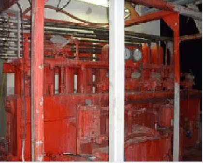
Accumulator
The storage device for nitrogen pressurized hydraulic fluid, which is used in operating the blowout preventers.
Annular Blowout Preventer
A large valve, usually installed above the ram preventers, that forms a seal in the annular space between the pipe and well bore. If no pipe is present, it forms a seal on the well bore itself.
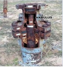
Annulus
The space around a pipe in a well bore, the outer wall of which may be the wall of either the bore hole or the casing; sometimes termed the annular space.
Blowout Preventer

A large valve, usually installed above the ram preventers, that forms a seal in the annular space between the pipe and well bore or, if no pipe is present, on the well bore itself.
Brake
The braking device on the drawworks to stop a load being
lifted.
Bulk Mud Components in Storage
Hopper type tanks for storage of drilling fluid components.
Casing Head
A heavy, flanged steel fitting connected to the first string of casing. It provides a housing for slips and packing assemblies, allows suspension of intermediate and production strings of casing, and supplies the means for the annulus to be sealed off. Also called a spool.
Cathead
A spool-shaped attachment on a winch around which rope for hoisting and pulling is wound.
Catline Boom and Hoist Line
A structural framework erected near the top of the derrick for lifting material.
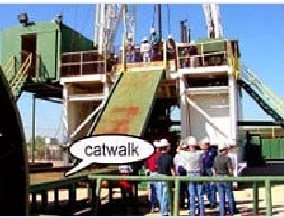
Catwalk
The ramp at the side of the drilling rig where pipe is laid to be lifted to the derrick floor by the catline or by an air hoist.
Cellar
A pit in the ground to provide additional height between the rig floor and the well head to accommodate the installation of blowout-preventers, ratholes, mouseholes,and so forth. It also collects drainage water and other fluids for disposal.
Choke Manifold
The arrangement of piping and special valves, called chokes, through which drilling mud is circulated when the blowout preventers are closed to control the pressures encountered during a kick. 
Conductor Pipe
The largest diameter casing and the topmost length of casing. It is relatively short and encases the topmost string of casing.
Crown Block and Water Table
An assembly of sheaves or pulleys mounted on beams at the top of the derrick. The drilling line is run over the sheaves down to the hoisting drum. 

Degasser
The equipment used to remove unwanted gas from a liquid, especially from drilling fluid.

Desander
A centrifugal device for removing sand from drilling fluid to prevent abrasion of the pumps. It may be operated mechanically or by a fast-moving stream of fluid inside a special cone-shaped vessel, in which case it is sometimes called a hydrocyclone.

Desilter
A centrifugal device, similar to a desander, used to remove very fine particles, or silt, from drilling fluid. This keeps the amount of solids in the fluid to the lowest possible level.

Doghouse
A small enclosure on the rig floor used as an office for the driller or as a storehouse for small objects. Also, any small building used as an office or for storage. 

Drawworks
The hoisting mechanism on a drilling rig. It is essentially a large winch that spools off or takes in the drilling line and thus raises or lowers the drill stem and bit. 

Drill Bit
The cutting or boring element used in drilling oil and gas wells. Most bits used in rotary drilling are roller-cone bits. The bit consists of the cutting elements and the circulating element. The circulating element permits the passage of drilling fluid and uses the hydraulic force of the fluid stream to improve drilling rates.

Drill Collar
A heavy, thick-walled tube, usually steel, used between the drill pipe and the bit in the drill stem. It is used to put weight on the bit so that the bit can drill.

Drill Pipe
The heavy seamless tubing used to rotate the bit and circulate the drilling fluid. Joints of pipe 30 feet long are coupled together with tool joints.
Driller's Console
The control panel, located on the platform, where the driller controls drilling operations.
Drilling Line
A wire rope hoisting line, reeved on sheaves of the crown block and traveling block (in effect a block and tackle). Its primary purpose is to hoist or lower drill pipe or casing from or into a well. Also, a wire rope used to support the drilling tools.

Electric Control House
On diesel electric rigs, powerful diesel engines drive large electric generators. The generators produce electricity that flows through cables to electric switches and control equipment enclosed in a control cabinet or panel. Electricity is fed to electric motors via the panel.

Electric Cable Tray
Supports the heavy electrical cables that feed the power from the control panel to the rig motors.

Elevators
A set of clamps that grips a stand, or column, of casing, tubing, drill pipe, or sucker rods, so the stand can be raised or lowered into the hole.
To Be Continued in the second Part. Leave your Comments
Read More HERE

Wednesday, December 11, 2013

'Door To Hell': Turkmenistan Crater Has Been On Fire For Over 40 Years

In 1971, the Soviets opened the Door to Hell, and 42 years later that door is still open. A natural gas field in Derweze, Turkmenistan, the Door to Hell is the site of a former Soviet oil operation that went wrong when a rig collapsed into a large crater. Soviet geologists decided the best thing to do was light the crater on fire to burn off its poisonous methane gas, but things didn't go as planned, and the fire still burns today.
The "Door to Hell" in Turkmenistan has been burning since 1971. Soviet geologists lit it on fire and thought it would only burn for a few days. (Photo: Wikimedia Commons)

Locals in Derweze, a village of about 350 souls, took to calling the site the Door to Hell, and its blaze can be seen from miles away. Located in Turkmenestan's Karakum Desert--a vast, sandy region with only one person per 2.5 square miles--the Door to Hell has become something of an unlikely tourist destination. One firsthand account of a visit to the Door to Hell comes from a 57-year-old Scotsman named Will Keeping.

"During daylight, I was initially not impressed as it looked like a hole in a vast desert," Keeping told The Daily Star. "As we got nearer and the glow from inside the carter became evident, though, and I started to notice the size of the crater and wondered how it could continually glow like that." Keeping added that as night came on, "the location slowly transformed from a large, isolated furnace in the middle of the desert into the center of attention that dominated the surrounding area--the glow became more intense and lit up the area including the sky above."

Another visitor to the the 200-foot wide, 70-foot-deep crater was Gurbanguly Berdimuhamedow, the president of of Turkmenistan. In 2010, Berdimuhamedow swung by the Door to Hell and ordered that the fiery crater be closed, but this hasn't happened.

While the 42-year Door to Hell fire is impressive, it pales in comparison to an American fire that has been going for more than half a century. On May 17, 1962, the fire department of the coal-mining town of Centralia, Penn., tried to clean up the town landfill by setting its contents on fire. The blaze ignited a coal seam and spread throughout the town's mines, releasing poisonous gasses and creating dangerous sinkholes. The town was condemned, and 1,400 Centralia residents left; a handful who remained were recently granted permission by the courts to keep their homes until their deaths.

Tuesday, December 10, 2013

Drilling and Completion of Multilateral Wells

MULTILATERAL
-Laterals are wellbores drilled from the main wellbore.
- Wellbores drilled from a horizontal lateral into the horizontal plane arebranches, those drilled from horizontal lateral into the vertical plane are splays.
-A multilateral well can follow different well trajectories: horizontal or deviated Junctions are the intersections of the laterals with the main wellbore or of the branches and splays with the lateral.


Multilateral Completion Systems
-Sperry-Sun drilling Services Company has developed two distinct completion systems for multilateral well bores which have full-open through-bore and re-entry capabilities. These systems are:
-Lateral-Tie Back System, LTBS.
-Retrievable Multi-Lateral System, RMLS.
-British Petroleum Co. (BP), has another system that is called "SRS", Selective Re-entry System for existing casing.
-This system was developed by Weatherford Services Co.

The Lateral-Tie Back System, LTBS

*This system consists of six main components
1.Pre-milled casing window joint.
2.drilling whipstock..
3.Lateral liner hanger.
4.Lateral liner running tool.
5.Cementing whipstock if drill with cemented Junctions.
6.Re-entry whipstock.

Retrievable Multi-Lateral System, RMLS
*The RMLS consists of four components
1.Casing window system.
2.Retrievable deflection tool (whipstock) incorporating.
3.Lateral liner transition joint.
4.Washover assembly.
Selective Re-entry System of Multilaterals
-Technologies were not developed that enabled drilling multilaterals into different producing reservoirs.
-SRS is the solution for increasing oil production and reserves from existing wells.

Technology Advancement Multilateral (TAML)
-Classified multilateral wells into seven categories (six levels with one sublevel) and provided a common language for operators and service companies to use when discussing multilateral completions.
-The definitions of the TAML levels were based on the amount and type of support and functionality provided at the junction in the well where one lateral wellbore merges with the main bore or with another lateral.

Technology Advancement of Multilaterals (TAML) levels
*Level 1:
is an open-hole lateral from an openhole mother bore.
-There is no mechanical or hydraulic junction involved.
-Carried out in consolidated formation as barefoot completions.
-widely applied in the United States, Canada, Europe, and the Middle East, with up to six lateral having been drilled from mother bore.
*Level 2:
main bore is cased in cemented and the lateral bore is open.
- The completion is economical, allows selective production, and can be carried out in standard casing sizes.
- United Arab Emirates wells have proven successful candidates for level 2.
*Level 3:
the main bore is cased and cemented, and the laterals are cased but not cemented.
-The lateral liner is mechanically anchored to the main bore using a liner hanger.
*level 4:
both the main bore and laterals are cased and cemented to providemechanical junction integrity.
-can be simple, or they can be the basis for more complex systems such as dual packers completions, single string selective reentries and single strings with lateral entry nipples.

*Level 5
Sealed junctions multilaterals are necessary for reservoir management and to handle complex geology in well environments with multiple pressures, fluids, and the rock strata.
-In these cases, pressure integrity is necessary to prevent junction collapse, due to pressure drawdown.
-Full hydraulic and mechanical pressure integrity at junction are achieved with completion.
*Level 6:
one in which junction pressure integrity is achieved with the casing and not by cement, which is not acceptable.
-The entire junction is an integral part of the main bore casing string.
-The first and most widely used level 6 system is the formation junction system.
-The system is run in a perforated mode as part of a standard casing or liner string, then reformed down hole using swaging technology.
-Conventional drilling, completion, and cementing techniques are used to finish construction and completion of well bore
Read More

Sunday, December 8, 2013

Horizontal drilling methods: Reason & methods

The choice of drilling method depends upon:
-Cost,
-Well spacing and
-Mechanical conditions of a vertical well bore
-In addition, reservoir consideration.


BUILD RATES
-Ultra-short Radius
-Short Radius
-Medium Radius
-Long Radius

ULTRA-SHORT RADIUS
-45 to 90 degrees per foot
-Special equipment
-Horizontal lengths of 100’ to 200’
-Used in unconsolidated, heavy oil sands and soft formation.
-Impossible to log the open hole section.

-An ultra-short radius drain hole is drilled using endless 1¼ inch tubing.
-Uses a jet under high pressure to cut the formation and advance the endless tubing.
- twenty-four laterals can be drilled at the same horizon.

SHORT RADIUS
-1.5 to 3 degrees per foot.
-Needs special equipment
-Mechanical and motor systems are available.
-Typically used in sidetracking existing wells to bypass water producing or troublesome.
-Bending stress and fatigue can be a problem
-200’ to 1000’ horizontal section
-The horizontal section can be cased with a slotted liner or left open hole.
-Open hole logging capabilities are limited for the horizontal section.

MEDIUM RADIUS
- The first medium radius wells were drilled in 1985
-6 to 35 degrees per 100’ build rates
-Uses conventional equipment
-Horizontal section lengths have been drilled over 7000’ but typically 2000’ to 4000’
LONG RADIUS
-2 to 6 degrees per 100’ build rates
-Uses conventional equipment
-Horizontal section lengths have been drilled over 10,000’ but typically 3000’ to 5000’
-No problem with bending stress, fatigue or completion equipment
-Build section is steerable, which means the motor can be rotated in the build section
-Offshore uses long radius almost exclusively since longer departures are required before the well gets to be horizontal
-Wells are more easily logged.
Read More Here

Sunday, December 1, 2013

Pipeline Risk Management Manual: Ideas, Techniques, and Resources

Here's the ideal tool if you're looking for a flexible, straightforward analysis system for your everyday design and operations decisions. This new third edition includes sections on stations, geographical information systems, "absolute" versus "relative" risks, and the latest regulatory developments. From design to day-to-day operations and maintenance, this unique volume covers every facet of pipeline risk management, arguably the most important, definitely the most hotly debated, aspect of pipelining today.
Written by: W. Kent Muhlbauer
No. of pages: 422

Now expanded and updated, this widely accepted standard reference guides you in managing the risks involved in pipeline operations. You'll also find ways to create a resource allocation model by linking risk with cost and customize the risk assessment technique to your specific requirements. The clear step-by-step instructions and more than 50 examples make it easy. This edition has been expanded to include offshore pipelines and distribution system pipelines as well as cross-country liquid and gas transmission pipelines.
The only comprehensive manual for pipeline risk managementUpdated material on stations, geographical information systems, "absolute" versus "relative" risks, and the latest regulatory developmentsSet the standards for global pipeline risk management
Download link is below post in First comment
Don't forget to leave your comment

Thursday, November 28, 2013

Causes of Kick (Wellbore Influx)

A “Kick” or “Wellbore Influx” is undesirable flow of formation fluid into the wellbore and it happens when formation pressure is more than hydrostatic pressure in wellbore.
Deepwater Horizon offshore drilling unit on fire 2010 (Wiki)

Several causes of Kick (Wellbore Influx) are listed below:
1. Lack of knowledge and experience of personnel (Human error)– Lacking of well-trained personnel can cause well control incident because they don’t have any ideas what can cause well control problem. For example, personnel may accidentally pump lighter fluid into wellbore and if the fluid is light enough, reservoir pressure can overcome hydrostatic pressure.

2. Light density fluid in wellbore - It results in decreasing hydrostatic pressure. There are several reasons that can cause this issue such as

• Light pills, sweep, spacer in hole

• Accidental dilution of drilling fluid

• Gas cut mud

3. Abnormal pressure – If abnormally high pressure zones are over current mud weight in the well, eventually kick will occur.

4. Unable to keep the hole full all the time while drilling and tripping. If hole is not full with drilling fluid, overall hydrostatic pressure will decrease.

5. Severe lost circulation – Due to lost circulation in formation, if the well could not be kept fully filled all the time, hydrostatic pressure will be decreased.

Lost circulation usually caused when the hydrostatic pressure of drilling fluid exceeds formation pressure. There are several factors that can cause lost circulation such as

• Mud properties – mud weight is too heavy and too viscous.

• High Equivalent Circulating Density

• High surge pressure due to tripping in hole so fast

• Drilling into weak formation strength zone

6. Swabbing causes reducing wellbore hydrostatic pressure.
Swabbing is the condition that happens when anything in a hole such as drill string, logging tool, completion sting, etc is pulled and it brings out decreasing hydrostatic pressure. Anyway, swabbing can be recognized while pulling out of hole by closely monitoring hole fill in trip sheet.
Related Topics

Tuesday, November 26, 2013

Schlumberger Open Recruitment 2014 : 2 positions

85 SCHLUMBERGER RECRUITING SESSIONPosition available:
FIELD SPECIALIST for Fresh Graduates
FIELD SPECIALIST for Mid Career


Requirements for Fresh Graduate Candidates:
• D3 and D-4 Polytechnic from all ENGINEERING Degree
• Dynamic men with maximum age of 26 years old
• Very good academic result, with minimum GPA 2.70
• Excellent command of English


Requirements for Mid Career Candidates:
• Dynamic men with max 3 year working experience in Oil & Gas Services
• D3 and D-4 Polytechnic from all ENGINEERING Degree
• Excellent command of English


Application Procedure:
• Interested candidates should send CVs to INGRecruiting@slb.com with email title format:
“Degree (D3/D4)_Years of Experience (0/1/2/3 years)_FS Application”
• Maximum CV size is 5 Mb.
• Registration will be closed on 04-Dec-2013


Chosen candidates will be invited to selection test by email therefore candidates need to check their emails regularly after applying.

Related Jobs

Saturday, November 16, 2013

Texas-Drilling Rig Hits Gas Pipeline Then Explodes

November 14th, 2013 MILFORD, Texas -Hundreds of people in Ellis County were evacuated and others were asked to stay away from the area where a gas pipeline caught fire Thursday morning.
It happened at about 9:30 a.m. November 14th, 2013 near the intersection of Highway 77 and FM 308 in Milford.
Ellis County spokesman James Saulter said a Chevron crew had been conducting a type of drilling when the explosion happened.
Video from SKY4 showed heavy flames rising from what appeared to a rig in a rural field. It was surrounded by several charred work trucks. The large plum of black smoke was visible from Interstate 35E.
No one was hurt and there were no reports of damage to any nearby homes or businesses, Saulter said.
However, officials are still concerned about the fire spreading to other pipelines in the area.
The whole city of Milford, which has a population of about 800, was evacuated. Students were moved to schools in the nearby town of Italy.
Traffic on FM 308 was rerouted between Highways 22 and 77. Motorists in the area were asked to use I-35E as an alternative to Hwy. 77.
Chevron will let the pipeline burn itself out, which is expect to take about 24 hours, Saulter said.
More Photos


Related Links

Share

Twitter Delicious Facebook Digg Stumbleupon Favorites More

Search This Blog

Loading

Subscribe via email

button_subscribenow.png (314×89) Learn petro engineering daily

Find Us on Facebook: