JOB & DATA Search

Here,Find what you want:
Showing posts with label drilling. Show all posts

Saturday, January 17, 2015

Aramco CEO Assures Employees of Company’s Strength

Saudi Aramco is well prepared to face the steep drop in oil prices in the short and medium term, and it has made some adjustments in light of the price fall, according to CEO Khalid A. Al-Falih.
Al-Falih said in a memo published in the company’s internal Arabic weekly magazineQafilah that he understands that the current market situation has created ambiguity among company employees and their families about the company's ability to cope with sharply lower oil prices. “That’s why I am here confirming to you that we have strengthened our position when oil prices were high, as we expected this scenario to happen,” Al-Falih said in the memo. “We are able to maintain our long-term commitments, and we will continue our work with high flexibility, efficiency, and wisdom.”
Despite the recent drop in oil prices, Saudi Aramco CEO Khalid A. Al-Falih said the company will "maintain [its] long-term commitments."
The current situation offers an opportunity for Saudi Aramco, he said. “For example, amid these circumstances, we will be able to execute our projects at lower prices because others will be obliged to postpone their projects. This will lead service providers to slash their prices in order to get work,” he said.
Al-Falih said he expects many oil and gas companies will lay off employees, which may offer an opportunity for Saudi Aramco. “We will be able to hire talented people and experts we need to keep our investments going on,” he said.
Meanwhile, Al-Falih said that his company made eight discoveries in 2014, which will help boost the company’s overall reserves. “In addition, our gas production capacity has hit historic levels at 8 billion cubic feet per day,” he said.

By: Abdelghani Henni is the Middle East Editor for the Journal of Petroleum Technology
SEE MORE BELOW

Friday, January 16, 2015

Schlumberger to cut 9,000 employees, including in Houston

HOUSTON – Oil field giant Schlumberger said Thursday it will cut approximately 9,000 employees – around 7.5 percent of its workforce around the globe – as both petroleum prices and oil-company spending nosedive.

Schlumberger’s profits fell 82 percent in the fourth quarter as it wrote down $1.7 billion in assets. It said it recorded a $296 million charge related to its headcount reduction.
Robert Drummond, President of Schlumberger North America (left) and Jeremy Aumaugher, South Division Operations Manager (Tom Reel/ San Antonio Express-News)

It’s very unfortunate, but this is definitely not going to be the last headcount reduction in 2015 in the energy space,” said Rob Desai, an analyst with Edward Jones. “The goal is to position the company to come out of this downturn stronger.”

The oil-tool maker banked $302 million, or 23 cents a share, in net income in the October-December period, compared to $1.66 billion, or $1.26 a share, in the same period in 2013. Its revenues were up from $11.9 billion to $12.6 billion.

The job reductions began in the fourth quarter and are expected to be completed later this year, Schlumberger spokesman Stephen Harris said in an email.

“These global reductions encompass many geographic regions in which we operate, including the Houston area,” Harris said. The company is “not releasing any details on exactly how many and where these reductions are coming from, however.”
The company took an $800 million impairment charge when it retired some of the seismic vessels from its fleet. Schlumberger also took a $472 million devaluation charge on the devaluation of Venezuela’s currency against the U.S. dollar. And it saw $199 million impairment charge as the value of an investment in the Eagle Ford Shale sunk.
Traders reversed a large portion of Wednesday’s rally in crude oil. Futures for international Brent crude fell $1.02 to $47.67 per barrel on London’s ICE Futures Europe market. U.S. benchmark West Texas Intermediate fell $2.23 to $46.25 a barrel on the New York Mercantile Exchange.
FOR MORE NEWS

Sunday, April 13, 2014

Types of Directional Drilling Profiles

There are four basic well profiles considered while planning a directional well. Here we are only going to have basic preview of these profiles and the design considerations will be covered in the coming posts.

TYPE I WELLS
Type I wells are made up of a kick off point, one buildup section and a tangent section up to the target. They are also called Build and Hold Trajectory or L Profile Wells (as it is L - shaped). These wells are drilled vertically from the surface to kick-off point at a relatively shallow depth. From the kick off point, the well is steadily and smoothly deflected until a maximum angle and the desired direction are achieved (BUILD). Then, if desired, casing is run and cemented. Further, the established angle and direction are maintained (HOLD) while drilling upto the target depth.

Usually this method is employed when drilling shallow wells with single producing zones.
TYPE II WELLS
Type II wells are made up of a vertical section, a kick- off point, a build-up section, a tangent section, a drop-off section and a hold section upto target. They are also called S Profile Wells (as they are S - shaped). Like Type I Wells, the Type II wells are drilled vertically from the surface to the kick-off point at a relatively shallow depth. From the kick off point, the well is steadily and smoothly deflected until a maximum angle and the desired direction are achieved (BUILD). The angle and direction are maintained until a specified depth and horizontal departure has been reached (HOLD). Then, the angle is steadily and smoothly dropped (DROP) until the well is near vertical. Finally the angle and direction is maintained till we reach the target depth.
A disadvantage of the Type II is that it will generate more torque and drag for the same horizontal departure.
Usually this method is employed to hit multiple targets or to avoid faulted region or to minimize the inclination in the zone which will be fractured during completion or for sidetracking.

TYPE III WELLS
Type III wells are made up of a vertical section, a deep kick off and a build up to target. They are also called Deep Kick off wells or J Profile wells (as they are J - shaped). They are similar to the Type I well except the kickoff point is at a deeper depth. The well is deflected at the kickoff point, and inclination is continually built through the target interval (BUILD). The inclinations are usually high and the horizontal departure low.
This type of well is generally used for multiple sand zones, fault drilling, salt dome drilling, and stratigraphic tests. It is not used very often.

TYPE IV WELLS
Type IV wells are made up of anyone of the above profiles plus a horizontal section within the reservoir. They are also called Horizontal wells or Horizontal Directional Wells. A horizontal well is a well which can have any one of the above profiles plus a horizontal section within the reservoir.
The horizontal section is usually drilled at 90 degrees and therefore the extra maths involved is quite simple as we only need the measured length of the horizontal section to calculate the total well departure and total measured depth.
The hole total TVD usually remains the same as the TVD of the well at the start of the horizontal section. However, if the horizontal section is not drilled at 90 degrees or there are dip variations within the reservoir, then the total hole TVD will be the sum of the TVD of the horizontal section and the TVD of the rest of the well.
Horizontal drilling is used to produce thin oil zones with water or gas coning problems, used to increase productivity from low permeability reservoirs by increasing the amount of formation exposed to the wellbore, used to maximize production from reservoirs which are not being efficiently drained by vertical wells and to connect the portions of the reservoir that are productive.
RELATED TOPICS

Tuesday, April 8, 2014

Wireline Log Quality Control Reference Manual by Schlumberger

This Log Quality Control Reference Manual (LQCRM) is the third edition of the log quality control specifications used by Schlumberger. It concisely provides information for the acquisition of high-quality data at the wellsite and its delivery within defined standards. The LQCRM also facilitates the validation of Schlumberger wireline logs at the wellsite or in the office.
Produced by: Schlumberger
Download link is below post in First comment
Don't forget to leave your comment

Saturday, April 5, 2014

Petroleum Engineering Handbook Vol.1

The Petroleum Engineering Handbook has long been recognized as a valuable, comprehensive reference book that offers practical day-to-day applications for students and experienced engineering professionals alike. This new edition, the first since 1987, has been greatly expanded and consists of seven volumes.
Drilling technology has evolved substantially over the years, from slide rules and hand calculations to advanced computer science and numerical analysis. This volume, the first drilling content to be included in the Petroleum Engineering Handbook, is intended to provide a snapshot of the drilling state of the art at the beginning of the 21st century.
Written by: H. B. Bradley
Contents: Drilling geoscience • Drilling fluids • Drilling fluid mechanics • Well control • Bit selection • Directional drilling • Casing and wellhead design • Cementing • Drilling problems • Well planning • Underbalanced drilling • Emerging technologies • Marine drilling • Data acquisition and interpretation • Coiled tubing
Download link is below post in First comment
Don't forget to leave your comment

Thursday, March 13, 2014

Standard Handbook of Petroleum and Natural Gas Engineering Edition 2

This new edition of the Standard Handbook of Petroleum and Natural Gas Engineering provides you with the best, state-of-the-art coverage for every aspect of petroleum and natural gas engineering. With thousands of illustrations and 1,600 information-packed pages, this text is a handy and valuable reference.
Written by over a dozen leading industry experts and academics, the Standard Handbook of Petroleum and Natural Gas Engineering provides the best, most comprehensive source of petroleum engineering information available. Now in an easy-to-use single volume format, this classic is one of the true "must haves" in any petroleum or natural gas engineer's library.
* A classic for the oil and gas industry for over 65 years!
* A comprehensive source for the newest developments, advances, and procedures in the petrochemical industry, covering everything from drilling and production to the economics of the oil patch.
* Everything you need - all the facts, data, equipment, performance, and principles of petroleum engineering, information not found anywhere else.
* A desktop reference for all kinds of calculations, tables, and equations that engineers need on the rig or in the office.
* A time and money saver on procedural and equipment alternatives, application techniques, and new approaches to problems.

ًWritten by: William C. Lyons, Ph.D., P.E.
Contents
Preface. RESERVOIR ENGINEERING. Basic Principles, Definitions, and Data. Formation Evaluation. Pressure Transient Testing of Oil and Gas Wells. Mechanisms and Recovery of Hydrocarbons by Natural Means. Material Balance and Volumetric Analysis. Decline-Curve Analysis. Reserve Estimates. Secondary Recovery. Fluid Movement in Waterflooded Reservoirs. Estimating Waterflood Residual Oil Saturation. Enhanced Oil Recovery Methods. References. PRODUCTION ENGINEERING. Properties of Hydrocarbon Mixtures. Flow of Fluids. Natural Flow Performance. Artificial Lift Methods. Stimulation and Remedial Operations. Surface Oil Production Systems. Gas Production Engineering. Corrosion and Scaling. Environmental Considerations. Offshore Operations. References. PETROLEUM ECONOMICS. Estimating Oil and Gas Reserves. Classification of Petroleum Products. Methods for Estimating Reserves. Non-Associated Gas Reservoirs. Production Stimulation.Determining the Value of Future Production. The Market for Petroleum. Economics and the Petroleum Engineer. Preparation of a Cash Flow. Valuation of Oil and Gas Properties. Risk Analysis. References. Appendix: Units and Conversions (SI). Index.
Download link is below post in First comment
Don't forget to leave your comment

Thursday, January 2, 2014

The Chemistry and Technology of Petroleum FOURTH EDITION

The Chemistry and Technology of Petroleum offers a 21st century perspective on the development of petroleum refining technologies.
The Chemistry and Technology of Petroleum traces the science of petroleum from its subterranean formation to the physicochemical properties and the production of numerous products and petrochemical intermediates.

Written by: James G. Speight
No. of Pages: 217
Presenting nearly 50 percent new material, The Chemistry and Technology of Petroleum emphasizes novel refining approaches that optimize efficiency and throughput.
Download link is below post in First comment
Don't forget to leave your comment

Perforations Part 1

Overview
Perforating is a critical part of any well completion process. The perforating process generates holes -perforation tunnels- in steel casing surrounding cement and the formation.

In the past, perforation was regarded simply as holes in steel casing made .By different methods. But perforation is not just a simple hole drilling process.Perforated completions play a crucial role in economic oil and gas production. Long term well productivity and efficient hydrocarbon recovery.
2.2. History of Perforation in Brief 
1. Prior to the early 1930's, casing could be perforated in place by mechanical perforators. These tools consisted of either a single blade or wheel-type knife which could be opened at the desired
level to cut vertical slots in the casing.

2. Bullet perforating equipment was developed in the early 1930's and has been in continuous and widespread use since that time.
-The major drawbacks with this method were that the bullet remained in the perforation tunnel, penetration was not very good, and some casings could not be perforated effectively.

3. After World War II the Monroe, or shaped – charge, principle was adapted to oil well work, and the resulting practice is now commonly referred to as jet perforating.
-The principle of the shaped charge was developed during World War II fo armor piercing shells used in bazookas to destroy tanks. This new technology allowed the oil producers to have some control over the perforating design (penetration and entry hole size) to optimize productivity.
2.3. Gun systems
2.3.1. Overview
In order to allow oil and gas to flow into the well, conduits need to be made into the formation. To do this, a gun is positioned across the producing formation and is detonated to create perforations through the casing and cement.
The guns used for this purpose are known as perforating guns.

2.3.2. Perforating guns are divided into two primary categories:
- Capsule guns
- Carrier guns

2.3.3. The perforating gun performance is affected by the
- Gun size
- Clearance
- Entrance hole diameter
- Shot density
- Gun phasing
- Perforating length
- Temperature rating
After firing the gun and while retrieving, unwanted solids enter into the wellbore or formation through perforating tunnels. These are called the perforating debris. Perforating debris can create problems in highly deviated or horizontal wellbores and can also create problems with the completion hardware.
Sources of debris are not only gun system, but also from the casing, cement and formation.

Gun hardware contributing to debris are:
- Gun body
- Shaped charge liner slug and jet
- Shaped charge cas
- Shaped charge retaining system (that holds the charge inside the gun).

2.3.4.1. Shaped charge liner
Perforating debris sources can be controlled if properly engineered.
Shape charge liner used in deep penetrating charges is made of powder metal, which eliminates the carrot and slug associated with liner penetration into the formation during charge detonation. Big hole charges us solid liners in order to produce large hole into the casing. However pf4621 power flow liners, produce big holes and yet leave no slugs into perforating tunnels, this new technology charge can replace the ultrapack charges. Attempts are made to contain the debris in the gun,
collect it after perforating or minimize the quantity expelled.
To address this problem of controlling the debris,

two methods are used. These are:
- Zinc casing method
- Patented packing method

Additional techniques that contribute to reduced perforating debris include powder metal liners and non-plastic charge retention systems. These recent innovations help in limiting problems arising from perforation debris.
2.3.4.1.1. SHAPED CHARGE THEORY
The ultimate goal of perforating is to provide adequate productivity. Test laboratories evolved over the years to provide means of predicting and improving well performance. Today, the performance of the charges is determined according to the procedures outlined in the API RP 43 (standard procedure for evaluation of well perforators) fifth edition, published in 1991. From Figure B1 it can be seen that the penetrating power of a cylinder of explosive is greatly increased by a cavity at
the end opposite to the detonator. Furthermore, placing a thin metallic liner in the cavity increases penetration. A typical shaped charge consists of four main components: a case, a high order explosive powder, primer and a liner, as shown in Figure shown
The case simply holds all the components together.
- The explosive (RDX, HMX and HNS) is a complex mixture designed to allow packing and shipping in the case.
- The primer is a purer mixture of explosive which is more sensitive to the detonation of the detonating cord.
- The liner is used to form a jet which physically does the perforating.
- The detonating cord, which is initiated by a blasting cap, detonates each charge.
The selection of explosive material is based on the well temperature and anticipated exposure time at that temperature (Figure B3). RDX, HMX and HNS are all explosives used in oil well shaped charge manufacture. For deep penetrating charges, the liner is made from a mixture of powdered metals pressed into the shape of a cone. High precision inthe pressing operation is required and it must be done in an extremely uniform and predictable manner. For Big Hole charges, the liner is
drawn from a solid sheet of metal into hemispherical, parabolic, or more complex shapes.
For each of the two types of charges, there is a trade-off between entrance hole size and penetration. The sequence of events in firing is illustrated in Figure B4 from top to bottom.
The detonator initiates the cord which detonates at a rate of approximately 7000 m/s (23,000 ft/sec.) The pressure impulse from this detonation initiates the primer in the charge and the
explosive begins to detonate along the length of the charge.
The high pressure wave 30x106 kPa, 4,500,000 psi) strikes the liner and propels it inward. The liner collapses from apex to skirt imparting momentum with a velocity approaching
2500 m/s (8000 ft/sec). At the point of impact on the axis the pressure increases to approximately 50x106 kPa (7,000,000 psi) and from this high pressure region, a small amount of material is
propelled out at velocities in excess of 7000 m/sec (23,000 ft/sec). As the liner collapses further down the cone, more and more material must be propelled by less and less explosive such that the
impact pressure is substantially less. Thus the tip of this so-called jet is travelling 20 times faster than the rear portion and gives the elongated shape to the jet. The penetration depth depends on this stretching action. As the liner walls collapse inward, the resultant collision along the axis divides the flow into two parts, as in Figure B5. The inner surface of the liner material forms
the penetrating jet which is squirted out along the charge. The outer surface of the liner, which was in contact with the explosive, forms a rear jet or slug which moves forward slower than the forward jet. In the zone of collision, where division of the material forming the jet and slug takes place, there is a neutral point which moves along the axis as the liner collapse process continues. The very fast jet impacting a casing generates a pressure of approximately 70x106 kPa (10,000,000 psi). At this pressure the steel casing flows plastically and the entrance hole is formed. A similar behavior occurs with formation material as the jet penetrates. In addition, crushing and compacting of the formation material around the perforation may also occur. The entire process from detonation to perforation completion takes from 100 to 300 microseconds. The jet material arriving last at the target, making the end of the perforation, comes from the skirt or base. As discrete portions of the jet strike at this end of the hole, they penetrate, expending their energy in the process.
Portions of the jet continue the penetration process, until the entire jet is expended.
The perforation occurs so fast that, essentially, no heat is transferred. Indeed, it has been demonstrated that a stack of telephone directories can be penetrated without singeing a single page. It follows that no fusing of formation material occurs during penetration. However, crushing and
compacting of formation material is to be expected, and will be reviewed later.
2.3.4.1.2. SHAPED CHARGE DESIGN
Liner aspects, such as geometry, angle, material, and distance from base to apex, as well as stand off, and explosive density are more important than the amount of explosive (Figure B7a). Only about 20% of the available explosive energy goes into the useful jet. It has been proven that properly designed charges can out perform poorly designed charges that have twice the explosive load.
This is important in situations where a higher explosive load causes casing damage. Once a charge is designed for entrance hole and penetration efficiency, manufacturing quality control and
consistency become significant in shaped charge performance. Perforation efficiency is accomplished with maximum penetration, uniform crushed zone, and minimal plugging due to slug debris. This is achieved by designing a liner that will provide a uniform jet diameter and velocity with little to no deviation from the conical liner axis. For example, it is critical that the liner thickness and density be precise around the cone at any given point away from the apex. Figure 7b is an example of a less desirable jet due to poor quality control.
Related Links

Thursday, December 26, 2013

Drilling and Completion of Horizontal Wells

Horizontal drilling is the process of steering a drill bit to follow horizontal path
oriented approximately 90° from vertical through the reservoir rock. The interest in
drilling horizontal wells can be attributed to the following major reasons:
-Enhancement in primary production.
-Enhancement in secondary production.
-Enhancement in ultimate recovery of hydrocarbon in place.
-Application of horizontal drilling


Contents
-Introduction    
-History of horizontal well technology    
-The main sections of horizontal well     
-Horizontal well patterns     
-Application of horizontal drilling     
-Drilling techniques    
-Completion techniques    
-Advantages and disadvantages    
-Horizontal well costs    
-Advances in horizontal well technology
Download link is below post in First comment
Don't forget to leave your comment

Tuesday, December 17, 2013

Types Of Drilling Rigs: Land Rigs

There are several types of drilling rigs, which lies under several categories for example:
-Land Rigs
-Marine Barg
-Marine Jack-up
*Here, there are some photos of Land Rig Types


Don't Forget to leave your comment
Read More Here

Sunday, December 15, 2013

Rig components; part 1

-Accumulator-Annulus-Blowout Preventer-Brake-Bulk Mud Components in Storage-Casing Head-Cathead-Catline Boom and Hoist Line-Catwalk-Cellar-Choke Manifold-Conductor Pipe-Crown Block and Water Table-Desander-Desilter-Doghouse-Drawworks-Drill Bit-Drill Collar-Drill Pipe-Driller's Console-Drilling Line-Electric Control House-Electric Cable Tray-Elevators
Accumulator
The storage device for nitrogen pressurized hydraulic fluid, which is used in operating the blowout preventers.
Annular Blowout Preventer
A large valve, usually installed above the ram preventers, that forms a seal in the annular space between the pipe and well bore. If no pipe is present, it forms a seal on the well bore itself.
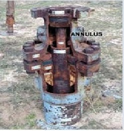
Annulus
The space around a pipe in a well bore, the outer wall of which may be the wall of either the bore hole or the casing; sometimes termed the annular space.
Blowout Preventer

A large valve, usually installed above the ram preventers, that forms a seal in the annular space between the pipe and well bore or, if no pipe is present, on the well bore itself.
Brake
The braking device on the drawworks to stop a load being
lifted.
Bulk Mud Components in Storage
Hopper type tanks for storage of drilling fluid components.
Casing Head
A heavy, flanged steel fitting connected to the first string of casing. It provides a housing for slips and packing assemblies, allows suspension of intermediate and production strings of casing, and supplies the means for the annulus to be sealed off. Also called a spool.
Cathead
A spool-shaped attachment on a winch around which rope for hoisting and pulling is wound.
Catline Boom and Hoist Line
A structural framework erected near the top of the derrick for lifting material.
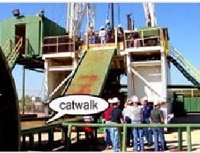
Catwalk
The ramp at the side of the drilling rig where pipe is laid to be lifted to the derrick floor by the catline or by an air hoist.
Cellar
A pit in the ground to provide additional height between the rig floor and the well head to accommodate the installation of blowout-preventers, ratholes, mouseholes,and so forth. It also collects drainage water and other fluids for disposal.
Choke Manifold
The arrangement of piping and special valves, called chokes, through which drilling mud is circulated when the blowout preventers are closed to control the pressures encountered during a kick. 
Conductor Pipe
The largest diameter casing and the topmost length of casing. It is relatively short and encases the topmost string of casing.
Crown Block and Water Table
An assembly of sheaves or pulleys mounted on beams at the top of the derrick. The drilling line is run over the sheaves down to the hoisting drum. 

Degasser
The equipment used to remove unwanted gas from a liquid, especially from drilling fluid.

Desander
A centrifugal device for removing sand from drilling fluid to prevent abrasion of the pumps. It may be operated mechanically or by a fast-moving stream of fluid inside a special cone-shaped vessel, in which case it is sometimes called a hydrocyclone.

Desilter
A centrifugal device, similar to a desander, used to remove very fine particles, or silt, from drilling fluid. This keeps the amount of solids in the fluid to the lowest possible level.

Doghouse
A small enclosure on the rig floor used as an office for the driller or as a storehouse for small objects. Also, any small building used as an office or for storage. 

Drawworks
The hoisting mechanism on a drilling rig. It is essentially a large winch that spools off or takes in the drilling line and thus raises or lowers the drill stem and bit. 

Drill Bit
The cutting or boring element used in drilling oil and gas wells. Most bits used in rotary drilling are roller-cone bits. The bit consists of the cutting elements and the circulating element. The circulating element permits the passage of drilling fluid and uses the hydraulic force of the fluid stream to improve drilling rates.

Drill Collar
A heavy, thick-walled tube, usually steel, used between the drill pipe and the bit in the drill stem. It is used to put weight on the bit so that the bit can drill.

Drill Pipe
The heavy seamless tubing used to rotate the bit and circulate the drilling fluid. Joints of pipe 30 feet long are coupled together with tool joints.
Driller's Console
The control panel, located on the platform, where the driller controls drilling operations.
Drilling Line
A wire rope hoisting line, reeved on sheaves of the crown block and traveling block (in effect a block and tackle). Its primary purpose is to hoist or lower drill pipe or casing from or into a well. Also, a wire rope used to support the drilling tools.

Electric Control House
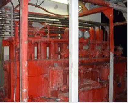
On diesel electric rigs, powerful diesel engines drive large electric generators. The generators produce electricity that flows through cables to electric switches and control equipment enclosed in a control cabinet or panel. Electricity is fed to electric motors via the panel.

Electric Cable Tray
Supports the heavy electrical cables that feed the power from the control panel to the rig motors.

Elevators
A set of clamps that grips a stand, or column, of casing, tubing, drill pipe, or sucker rods, so the stand can be raised or lowered into the hole.
To Be Continued in the second Part. Leave your Comments
Read More HERE

Wednesday, December 11, 2013

'Door To Hell': Turkmenistan Crater Has Been On Fire For Over 40 Years

In 1971, the Soviets opened the Door to Hell, and 42 years later that door is still open. A natural gas field in Derweze, Turkmenistan, the Door to Hell is the site of a former Soviet oil operation that went wrong when a rig collapsed into a large crater. Soviet geologists decided the best thing to do was light the crater on fire to burn off its poisonous methane gas, but things didn't go as planned, and the fire still burns today.
The "Door to Hell" in Turkmenistan has been burning since 1971. Soviet geologists lit it on fire and thought it would only burn for a few days. (Photo: Wikimedia Commons)

Locals in Derweze, a village of about 350 souls, took to calling the site the Door to Hell, and its blaze can be seen from miles away. Located in Turkmenestan's Karakum Desert--a vast, sandy region with only one person per 2.5 square miles--the Door to Hell has become something of an unlikely tourist destination. One firsthand account of a visit to the Door to Hell comes from a 57-year-old Scotsman named Will Keeping.

"During daylight, I was initially not impressed as it looked like a hole in a vast desert," Keeping told The Daily Star. "As we got nearer and the glow from inside the carter became evident, though, and I started to notice the size of the crater and wondered how it could continually glow like that." Keeping added that as night came on, "the location slowly transformed from a large, isolated furnace in the middle of the desert into the center of attention that dominated the surrounding area--the glow became more intense and lit up the area including the sky above."

Another visitor to the the 200-foot wide, 70-foot-deep crater was Gurbanguly Berdimuhamedow, the president of of Turkmenistan. In 2010, Berdimuhamedow swung by the Door to Hell and ordered that the fiery crater be closed, but this hasn't happened.

While the 42-year Door to Hell fire is impressive, it pales in comparison to an American fire that has been going for more than half a century. On May 17, 1962, the fire department of the coal-mining town of Centralia, Penn., tried to clean up the town landfill by setting its contents on fire. The blaze ignited a coal seam and spread throughout the town's mines, releasing poisonous gasses and creating dangerous sinkholes. The town was condemned, and 1,400 Centralia residents left; a handful who remained were recently granted permission by the courts to keep their homes until their deaths.

Tuesday, December 10, 2013

Drilling and Completion of Multilateral Wells

MULTILATERAL
-Laterals are wellbores drilled from the main wellbore.
- Wellbores drilled from a horizontal lateral into the horizontal plane arebranches, those drilled from horizontal lateral into the vertical plane are splays.
-A multilateral well can follow different well trajectories: horizontal or deviated Junctions are the intersections of the laterals with the main wellbore or of the branches and splays with the lateral.


Multilateral Completion Systems
-Sperry-Sun drilling Services Company has developed two distinct completion systems for multilateral well bores which have full-open through-bore and re-entry capabilities. These systems are:
-Lateral-Tie Back System, LTBS.
-Retrievable Multi-Lateral System, RMLS.
-British Petroleum Co. (BP), has another system that is called "SRS", Selective Re-entry System for existing casing.
-This system was developed by Weatherford Services Co.

The Lateral-Tie Back System, LTBS

*This system consists of six main components
1.Pre-milled casing window joint.
2.drilling whipstock..
3.Lateral liner hanger.
4.Lateral liner running tool.
5.Cementing whipstock if drill with cemented Junctions.
6.Re-entry whipstock.

Retrievable Multi-Lateral System, RMLS
*The RMLS consists of four components
1.Casing window system.
2.Retrievable deflection tool (whipstock) incorporating.
3.Lateral liner transition joint.
4.Washover assembly.
Selective Re-entry System of Multilaterals
-Technologies were not developed that enabled drilling multilaterals into different producing reservoirs.
-SRS is the solution for increasing oil production and reserves from existing wells.

Technology Advancement Multilateral (TAML)
-Classified multilateral wells into seven categories (six levels with one sublevel) and provided a common language for operators and service companies to use when discussing multilateral completions.
-The definitions of the TAML levels were based on the amount and type of support and functionality provided at the junction in the well where one lateral wellbore merges with the main bore or with another lateral.

Technology Advancement of Multilaterals (TAML) levels
*Level 1:
is an open-hole lateral from an openhole mother bore.
-There is no mechanical or hydraulic junction involved.
-Carried out in consolidated formation as barefoot completions.
-widely applied in the United States, Canada, Europe, and the Middle East, with up to six lateral having been drilled from mother bore.
*Level 2:
main bore is cased in cemented and the lateral bore is open.
- The completion is economical, allows selective production, and can be carried out in standard casing sizes.
- United Arab Emirates wells have proven successful candidates for level 2.
*Level 3:
the main bore is cased and cemented, and the laterals are cased but not cemented.
-The lateral liner is mechanically anchored to the main bore using a liner hanger.
*level 4:
both the main bore and laterals are cased and cemented to providemechanical junction integrity.
-can be simple, or they can be the basis for more complex systems such as dual packers completions, single string selective reentries and single strings with lateral entry nipples.

*Level 5
Sealed junctions multilaterals are necessary for reservoir management and to handle complex geology in well environments with multiple pressures, fluids, and the rock strata.
-In these cases, pressure integrity is necessary to prevent junction collapse, due to pressure drawdown.
-Full hydraulic and mechanical pressure integrity at junction are achieved with completion.
*Level 6:
one in which junction pressure integrity is achieved with the casing and not by cement, which is not acceptable.
-The entire junction is an integral part of the main bore casing string.
-The first and most widely used level 6 system is the formation junction system.
-The system is run in a perforated mode as part of a standard casing or liner string, then reformed down hole using swaging technology.
-Conventional drilling, completion, and cementing techniques are used to finish construction and completion of well bore
Read More

Share

Twitter Delicious Facebook Digg Stumbleupon Favorites More

Search This Blog

Loading

Subscribe via email

button_subscribenow.png (314×89) Learn petro engineering daily

Find Us on Facebook: