During drilling operations, a pipe is considered stuck if it cannot be freed and pulled out of the hole without damaging the pipe and without exceeding the drilling rig’s maximum allowed hook load. Differential pressure pipe sticking and mechanical pipe sticking are addressed in this section.
Differential-Pressure Pipe Sticking
Differential-pressure pipe sticking occurs when a portion of the drillstring becomes embedded in a mudcake (an impermeable film of fine solids) that forms on the wall of a permeable formation during drilling. If the mud pressure, pm , which acts on the outside wall of the pipe, is greater than the formation-fluid pressure, pff , which generally is the case (with the exception of underbalanced drilling), then the pipe is said to be differentially stuck (see Fig. below). The differential pressure acting on the portion of the drillpipe that is embedded in the mudcake can be expressed as

 ....................(10.1)
The pull force, Fp, required to free the stuck pipe is a function of the differential pressure, Δp; the coefficient of friction, f; and the area of contact, Ac, between the pipe and mudcake surfaces.
 ....................(10.2)
From Bourgoyne[1],
 ....................(10.3)
where
 ....................(10.4)
In this formula, Lep is the length of the permeable zone, Dop is the outside diameter of the pipe, Dh is the diameter of the hole, and hmcis the mudcake thickness. The dimensionless coefficient of friction, f, can vary from less than 0.04 for oil-based mud to as much as 0.35 for weighted water-based mud with no added lubricants.
Eqs. 10.2 and 10.3 show controllable parameters that will cause higher pipe-sticking force and the potential inability of freeing the stuck pipe. These parameters are unnecessarily high differential pressure, thick mudcake (high continuous fluid loss to formation), low-lubricity mudcake (high coefficient of friction), and excessive embedded pipe length in mudcake (delay of time in freeing operations).
Although hole and pipe diameters and hole angle play a role in the pipe-sticking force, they are uncontrollable variables once they are selected to meet well design objectives. However, the shape of drill collars, such as square, or the use of drill collars with spiral grooves and external-upset tool joints can minimize the sticking force.
Some of the indicators of differential-pressure-stuck pipe while drilling permeable zones or known depleted-pressure zones are an increase in torque and drag; an inability to reciprocate the drillstring and, in some cases, to rotate it; and uninterrupted drilling-fluid circulation. Differential-pressure pipe sticking can be prevented or its occurrence mitigated if some or all of the following precautions are taken:
-Maintain the lowest continuous fluid loss adhering to the project economic objectives.
-Maintain the lowest level of drilled solids in the mud system, or, if economical, remove all drilled solids.
-Use the lowest differential pressure with allowance for swab and surge pressures during tripping operations.
-Select a mud system that will yield smooth mudcake (low coefficient of friction).
-Maintain drillstring rotation at all times, if possible.
Differential-pressure-pipe-sticking problems may not be totally prevented. If sticking does occur, common field practices for freeing the stuck pipe include mud-hydrostatic-pressure reduction in the annulus, oil spotting around the stuck portion of the drillstring, and washing over the stuck pipe. Some of the methods used to reduce the hydrostatic pressure in the annulus include reducing mud weight by dilution, reducing mud weight by gasifying with nitrogen, and placing a packer in the hole above the stuck point.
Differential-Pressure Pipe Sticking
Differential-pressure pipe sticking occurs when a portion of the drillstring becomes embedded in a mudcake (an impermeable film of fine solids) that forms on the wall of a permeable formation during drilling. If the mud pressure, pm , which acts on the outside wall of the pipe, is greater than the formation-fluid pressure, pff , which generally is the case (with the exception of underbalanced drilling), then the pipe is said to be differentially stuck (see Fig. below). The differential pressure acting on the portion of the drillpipe that is embedded in the mudcake can be expressed as

 ....................(10.1)
The pull force, Fp, required to free the stuck pipe is a function of the differential pressure, Δp; the coefficient of friction, f; and the area of contact, Ac, between the pipe and mudcake surfaces.
 ....................(10.2)
 From Bourgoyne[1],
 ....................(10.3)
 where
 ....................(10.4)
 In this formula, Lep is the length of the permeable zone, Dop is the outside diameter of the pipe, Dh is the diameter of the hole, and hmcis the mudcake thickness. The dimensionless coefficient of friction, f, can vary from less than 0.04 for oil-based mud to as much as 0.35 for weighted water-based mud with no added lubricants.
Eqs. 10.2 and 10.3 show controllable parameters that will cause higher pipe-sticking force and the potential inability of freeing the stuck pipe. These parameters are unnecessarily high differential pressure, thick mudcake (high continuous fluid loss to formation), low-lubricity mudcake (high coefficient of friction), and excessive embedded pipe length in mudcake (delay of time in freeing operations).
Although hole and pipe diameters and hole angle play a role in the pipe-sticking force, they are uncontrollable variables once they are selected to meet well design objectives. However, the shape of drill collars, such as square, or the use of drill collars with spiral grooves and external-upset tool joints can minimize the sticking force.
Some of the indicators of differential-pressure-stuck pipe while drilling permeable zones or known depleted-pressure zones are an increase in torque and drag; an inability to reciprocate the drillstring and, in some cases, to rotate it; and uninterrupted drilling-fluid circulation. Differential-pressure pipe sticking can be prevented or its occurrence mitigated if some or all of the following precautions are taken:
-Maintain the lowest continuous fluid loss adhering to the project economic objectives.
-Maintain the lowest level of drilled solids in the mud system, or, if economical, remove all drilled solids.
-Use the lowest differential pressure with allowance for swab and surge pressures during tripping operations.
-Select a mud system that will yield smooth mudcake (low coefficient of friction).
-Maintain drillstring rotation at all times, if possible.
Differential-pressure-pipe-sticking problems may not be totally prevented. If sticking does occur, common field practices for freeing the stuck pipe include mud-hydrostatic-pressure reduction in the annulus, oil spotting around the stuck portion of the drillstring, and washing over the stuck pipe. Some of the methods used to reduce the hydrostatic pressure in the annulus include reducing mud weight by dilution, reducing mud weight by gasifying with nitrogen, and placing a packer in the hole above the stuck point.
Mechanical Pipe Sticking
The causes of mechanical pipe sticking are inadequate removal of drilled cuttings from the annulus; borehole instabilities, such as hole caving, sloughing, or collapse; plastic shale or salt sections squeezing (creeping); and key seating.
Drilled Cuttings. Excessive drilled-cuttings accumulation in the annular space caused by improper cleaning of the hole can cause mechanical pipe sticking, particularly in directional-well drilling. The settling of a large amount of suspended cuttings to the bottom when the pump is shut down or the downward sliding of a stationary-formed cuttings bed on the low side of a directional well can pack a bottomhole assembly (BHA), which causes pipe sticking. In directional-well drilling, a stationary cuttings bed may form on the low side of the borehole (see Fig. below). If this condition exists while tripping out, it is very likely that pipe sticking will occur. This is why it is a common field practice to circulate bottom up several times with the drill bit off bottom to flush out any cuttings bed that may be present before making a trip. Increases in torque/drag and sometimes in circulating drillpipe pressure are indications of large accumulations of cuttings in the annulus and of potential pipe-sticking problems.
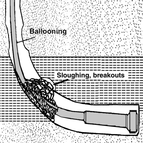
 Borehole Instability: This topic is addressed in Sec. 10.6; however, it is important to mention briefly the pipe-sticking issues associated with the borehole-instability problems. The most troublesome issue is that of drilling shale. Depending on mud composition and mud weight, shale can slough in or plastically flow inward, which causes mechanical pipe sticking. In all formation types, the use of a mud that is too low in weight can lead to the collapse of the hole, which can cause mechanical pipe sticking. Also, when drilling through salt that exhibits plastic behavior under overburden pressure, if mud weight is not high enough, the salt has the tendency of flowing inward, which causes mechanical pipe sticking. Indications of a potential pipe-sticking problem caused by borehole instability are a rise in circulating drillpipe pressure, an increase in torque, and, in some cases, no fluid return to surface. (Fig. below) illustrates pipe sticking caused by wellbore instability.
 Key Seating: Key seating is a major cause of mechanical pipe sticking. The mechanics of key seating involve wearing a small hole (groove) into the side of a full-gauge hole. This groove is caused by the drillstring rotation with side force acting on it. (Fig. Below)illustrates pipe sticking caused by key seating. This condition is created either in doglegs or in undetected ledges near washouts. The lateral force that tends to push the pipe against the wall, which causes mechanical erosion and thus creates a key seat, is given by

 ....................(10.5)
where Fl is the lateral force, T is the tension in the drillstring just above the key-seat area, and ϴdl is the abrupt change in hole angle (commonly referred to as dogleg angle).
Generally, long bit runs can cause key seats; therefore, it is common practice to make wiper trips. Also, the use of stiffer BHAs tends to minimize severe dogleg occurrences. During tripping out of hole, a key-seat pipe-sticking problem is indicated when several stands of pipe have been pulled out, and then, all of a sudden, the pipe is stuck.
Freeing mechanically stuck pipe can be undertaken in a number of ways, depending on what caused the sticking. For example, if cuttings accumulation or hole sloughing is the suspected cause, then rotating and reciprocating the drillstring and increasing flow rate without exceeding the maximum allowed equivalent circulating density (ECD) is a possible remedy for freeing the pipe. If hole narrowing as a result of plastic shale is the cause, then an increase in mud weight may free the pipe. If hole narrowing as a result of salt is the cause, then circulating fresh water can free the pipe. If the pipe is stuck in a key-seat area, the most likely successful solution is backing off below the key seat and going back into the hole with an opener to drill out the key section. This will lead to a fishing operation to retrieve the fish. The decision on how long to continue attempting to free stuck pipe vs. back off, plug back, and then sidetrack is an economic issue that generally is addressed by the operating company.
The causes of mechanical pipe sticking are inadequate removal of drilled cuttings from the annulus; borehole instabilities, such as hole caving, sloughing, or collapse; plastic shale or salt sections squeezing (creeping); and key seating.
Drilled Cuttings. Excessive drilled-cuttings accumulation in the annular space caused by improper cleaning of the hole can cause mechanical pipe sticking, particularly in directional-well drilling. The settling of a large amount of suspended cuttings to the bottom when the pump is shut down or the downward sliding of a stationary-formed cuttings bed on the low side of a directional well can pack a bottomhole assembly (BHA), which causes pipe sticking. In directional-well drilling, a stationary cuttings bed may form on the low side of the borehole (see Fig. below). If this condition exists while tripping out, it is very likely that pipe sticking will occur. This is why it is a common field practice to circulate bottom up several times with the drill bit off bottom to flush out any cuttings bed that may be present before making a trip. Increases in torque/drag and sometimes in circulating drillpipe pressure are indications of large accumulations of cuttings in the annulus and of potential pipe-sticking problems.


 ....................(10.5)
 where Fl is the lateral force, T is the tension in the drillstring just above the key-seat area, and ϴdl is the abrupt change in hole angle (commonly referred to as dogleg angle).
Generally, long bit runs can cause key seats; therefore, it is common practice to make wiper trips. Also, the use of stiffer BHAs tends to minimize severe dogleg occurrences. During tripping out of hole, a key-seat pipe-sticking problem is indicated when several stands of pipe have been pulled out, and then, all of a sudden, the pipe is stuck.
Freeing mechanically stuck pipe can be undertaken in a number of ways, depending on what caused the sticking. For example, if cuttings accumulation or hole sloughing is the suspected cause, then rotating and reciprocating the drillstring and increasing flow rate without exceeding the maximum allowed equivalent circulating density (ECD) is a possible remedy for freeing the pipe. If hole narrowing as a result of plastic shale is the cause, then an increase in mud weight may free the pipe. If hole narrowing as a result of salt is the cause, then circulating fresh water can free the pipe. If the pipe is stuck in a key-seat area, the most likely successful solution is backing off below the key seat and going back into the hole with an opener to drill out the key section. This will lead to a fishing operation to retrieve the fish. The decision on how long to continue attempting to free stuck pipe vs. back off, plug back, and then sidetrack is an economic issue that generally is addressed by the operating company.
To Be Continued in the second Part. Leave your Comments
Read More HERE
Read More HERE